The short answer
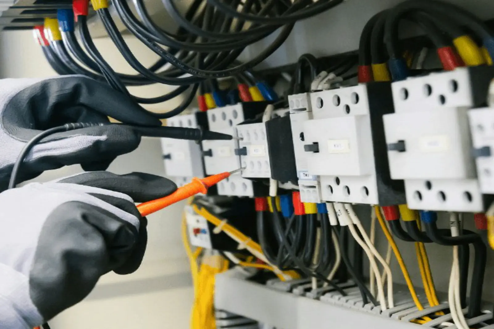
A ground fault trip means the drive has found current flowing to earth from its output, so the motor cable and the motor are the first suspects; an overcurrent trip means the output current went past the drive's limit, from a short, too much load or settings such as a too-short acceleration time or a wrong boost setting. Read the drive's fault record first – the code, and on many drives the current and bus voltage at the trip – then check the motor and cable with the drive locked out. An insulation test is for a qualified person, with the drive locked out and the motor leads disconnected from it – an insulation tester can damage the drive.
Every code, parameter and step here, except the steps marked as common practice, comes from the makers' manuals: Allen-Bradley PowerFlex 4, 40, 525, 70 and 750-series drives and Siemens SINAMICS G120 with CU240B-2 / CU240E-2 control units.
Key takeaways
- Read the fault record before you reset: the code plus the current and bus voltage at the trip tell you where to look.
- Ground fault means current to earth; overcurrent means too much current in the phases.
- Never run an insulation test through the drive: lock out, have a qualified person verify zero with a rated meter, and disconnect the motor leads first.
What the codes mean
| Drive | Ground fault | Overcurrent | Also |
|---|---|---|---|
| PowerFlex 4 / 40 | F13 Ground Fault | F12 HW OverCurrent | F38–F40 one phase to ground; F41–F43 two phases shorted; F63 SW OverCurrent (A098 trip level) |
| PowerFlex 525 | F013 Ground Fault | F012 HW OverCurrent | F038–F043 as above; F063 SW OverCurrent (shear pin) |
| PowerFlex 70 | F13: more than 25 % of drive rating to earth | F12 HW OverCurrent | F36 SW OverCurrent: the 1 ms rating, typically 200–250 % of continuous |
| PowerFlex 750 | F13: more than 25 % of drive rating to earth | F12 HW OverCurrent | For both, Rockwell adds an insulation-resistance check of the motor wiring – locked out, by a qualified person |
| SINAMICS G120 | F30021 Power unit: Ground fault | F30001 Power unit: Overcurrent | F07801 Motor overcurrent (the motor current limit) |
The phase codes name the phase. For F38–F40 Rockwell's steps are the wiring between drive and motor, then the motor, then the drive if the fault can't be cleared.
Read the drive before you touch the wiring
- PowerFlex 4 / 40: d007–d009 [Fault 1–3 Code], d007 the most recent.
- PowerFlex 525: b007–b009 and F604–F610 hold ten fault codes; for the latest trip, F631 [Fault 1 Freq], F641 [Fault 1 Current] and F651 [Fault 1 BusVolts] keep the frequency, current and DC bus voltage.
- PowerFlex 70: parameters 243, 245, 247 and 249 [Fault 1–4 Code].
- PowerFlex 750: P951 [Last Fault Code] is the first fault after the most recent reset; the fault queue has the history.
- SINAMICS G120: r0945 is the fault code, r0949 the fault value, r0948 the time. On F30001, bits 0–2 of r0949 name phase U, V or W and bit 3 the DC link (0: phase not identified). On F30021, 0 means the hardware DC current monitoring or a shorted braking resistor; above 0 it is the summation current (32767 = 271 % of rated current).
Ground fault: first checks
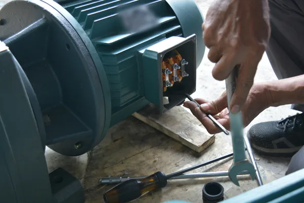
- Motor and output wiring: a grounded condition in the cable or motor first. Siemens adds a defective current transformer, the brake wiring and a shorted braking resistor.
- Residual-current devices: on the PowerFlex 4, 40 and 525, use only Type B (adjustable) RCDs upstream to avoid nuisance trips.
- PowerFlex 525 with a permanent-magnet motor: F012 or F013 during acceleration or deceleration means the PM angle alignment failed; the manual's adjustments are more PM DC injection current (A517) and a longer align time (A518).
- PowerFlex 755, frame 8 and larger: for inverter ground faults, Rockwell's steps include a Megger or surge test on the disconnected motor – locked out, by a qualified person – and comparing the three phase currents for imbalance.
Overcurrent: first checks
- Shorts: in the drive output and motor wiring.
- Settings: boost (A084 on PowerFlex 4 / 40, A530 on the 525), DC brake voltage set too high; on a G120 in U/f mode, a too-short ramp-up time (p1120) and the current limit (p0640).
- Sizing and cabling: on a G120, a motor rated far above the power unit (U/f mode), power cables over the permitted length, a missing line reactor at switch-on or a lost line phase.
- Load: excess load or a jam. F063 on a PowerFlex 525 is the shear pin: check the motor-to-load connection and the setting.
- Spinning motor: on a G120, starting into a turning motor without flying restart (p1200) can cause F07801.
Insulation checks without damaging the drive
- Lock out the drive's supply and wait for the DC bus to discharge: three minutes on a PowerFlex 525, up to five on a G120 PM240-2, or the time on the drive's label.
- At the line, output and DC bus terminals, a qualified person verifies zero voltage with a properly rated meter, checking the meter on a known source before and after.
- Disconnect the motor leads from the drive's output terminals. Siemens warns that a wrong insulation test can damage the drive and says to disconnect it first; Rockwell's PowerFlex 750-series manual (750-PM001Q, p. 336) describes it on a disconnected motor.
- With the drive still locked out, a qualified person tests the cable and motor from the disconnected leads to ground. Common practice, not from these drive manuals: label the leads before you lift them, test the cable and the motor separately to see which one is at fault, discharge the cable and motor to ground after the test (the tester leaves a charge), and take the test voltage and the acceptable reading from the motor maker's data and your site's procedure.
First checks
- Fault code, and the current and bus voltage at the trip where the drive keeps them.
- Motor cable: damage, wet conduit, loose or burned terminations.
- Settings and load: acceleration time, boost, DC brake; a jammed machine.
- Insulation of cable and motor: locked out, drive disconnected, by a qualified person.
Fault codes on specific drives: PowerFlex 525, PowerFlex 4 and 40, PowerFlex 70, PowerFlex 753 and SINAMICS G120 / S120.
Safety first: only qualified personnel should work on drives and motors, and any measurement on energized equipment follows your site's live-work and arc-flash rules – insulation is measured only with power locked out, never on a live circuit. Lock out the drive's supply following the manufacturer's instructions and your site's lockout/tagout procedure, wait the DC bus discharge time on the drive's label, and a qualified person verifies zero voltage with a properly rated meter, checking the meter on a known source before and after, before anyone touches the terminals. Don't reset a ground fault over and over to keep a machine running, and never force outputs or bypass a safety circuit.
Parts that commonly fail
Drives and their power and control units are the hardware behind many of these trips. The part numbers we have the most of in stock right now:
PowerFlex 40 drives
PowerFlex 4 drives
PowerFlex 70 drives
- 20AD3P4A0AYNNNNNAllen-Bradley 20AD3P4A0AYNNNNN PowerFlex 70 AC Drive 2HP 480V 3…
- 20AD3P4A3AYYNDNNAllen-Bradley 20AD3P4A3AYYNDNN PowerFlex 70 VFD 2HP 480V 3.4A w…
- 20AD011A3AYNACNNAllen-Bradley 20AD011A3AYNACNN PowerFlex 70 VFD 7.5HP 480V 3-Ph…
- 20AD014F0AYNANC0Allen-Bradley 20AD014F0AYNANC0 PowerFlex 70 AC VFD 480V 3PH 14A…
SINAMICS G120 power and control units
Stock changes every day. Every listing is photographed, so check the catalog number, series or product version and firmware on the label photo before you buy.
Not listed, or need several? Send us the part number and we'll check our shelves and our sourcing network and quote it in writing.
Sources
Every code, LED state and menu path on this page was checked against Rockwell Automation's and Siemens' own documents, listed below, and is described here in our own words. Manuals change between editions and firmware revisions: for your exact catalog or order number, check the current edition.
- Rockwell Automation, PowerFlex 520-Series Adjustable Frequency AC Drive User Manual, publication 520-UM001O-EN-E, September 2025.
- Rockwell Automation, PowerFlex 4 Adjustable Frequency AC Drive User Manual, publication 22A-UM001L-EN-E, September 2024.
- Rockwell Automation, PowerFlex 40 Adjustable Frequency AC Drive User Manual, publication 22B-UM001J-EN-E, September 2025.
- Rockwell Automation, PowerFlex 70 Adjustable Frequency AC Drives User Manual, publication 20A-UM001P-EN-P, February 2018.
- Rockwell Automation, PowerFlex 750-Series AC Drives Programming Manual, publication 750-PM001Q-EN-P, November 2024.
- Siemens, SINAMICS G120 Control Units CU240B-2/CU240E-2 List Manual, edition 02/2023, A5E33839529, entry 109817919.
- Siemens, SINAMICS G120 Power Module PM240-2 Hardware Installation Manual, edition 08/2017, A5E33294624B AG, entry 109750315.
Frequently asked questions
What causes a ground fault trip on a VFD?
Current flowing to earth from the drive output: suspect the motor cable and the motor first; Siemens adds a defective current transformer, the brake wiring and a shorted braking resistor. A qualified person checks them with the drive locked out and the motor leads disconnected.
What is the difference between F012 and F063 on a PowerFlex 525?
F012 HW OverCurrent means the output current went past the drive's hardware current limit: check the load, the boost setting (A530) and the DC brake voltage. F063 SW OverCurrent is the shear pin function: the level set in A486 or A488 was exceeded for longer than A487 or A489 allows, so check the motor-to-load connection and the settings.
Can I megger a motor while it is connected to the VFD?
No. Lock out the drive, wait for the DC bus to discharge, have a qualified person verify zero voltage with a rated meter and disconnect the motor leads from the drive's output terminals first. Siemens warns that a wrong insulation test can damage the drive, and Rockwell's PowerFlex 750 manual describes the test on a disconnected motor.
Which parameter shows the last fault on a PowerFlex drive?
PowerFlex 4 and 40: d007 [Fault 1 Code]. PowerFlex 525: b007 [Fault 1 Code], with the current and bus voltage at the trip in F641 and F651. PowerFlex 70: parameter 243 [Fault 1 Code]. PowerFlex 750: P951 [Last Fault Code], the first fault after the most recent reset.