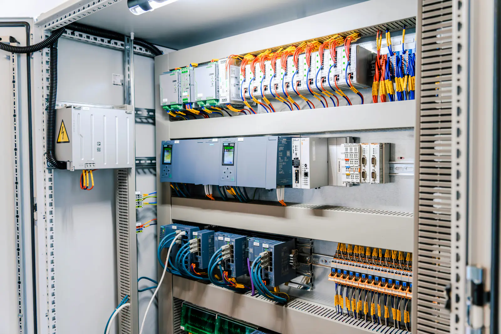
The short answer
An I/O module that is faulted or not responding may be missing power, not fully seated, in a different slot from the one configured, a different module from the one configured, or reporting a fault in its field wiring. On a ControlLogix module, a flashing red OK LED means its connection timed out and a steady red one means Rockwell says to replace the module; Studio 5000 shows the reason as a code such as 16#0204 (module not answering) or 16#0114 (keying mismatch). On Siemens modules, a red SF LED (S7-300) or a flashing ERROR LED (S7-1500) means the module has a diagnostic message you can read in STEP 7 or TIA Portal.
This covers Allen-Bradley ControlLogix (1756) and SLC 500 (1746) I/O and Siemens S7-300 and S7-1500 signal modules. If the controller itself has stopped, start with ControlLogix major fault codes or S7-300 SF and BF LEDs.
Key takeaways
- Read the module's own LEDs first – OK on Allen-Bradley, SF or RUN/ERROR on Siemens – then the code or diagnostic message in the software.
- Power, seating, the slot and keying can each make a good module look dead – check them before you order a replacement.
- Don't make a module connect by setting Disable Keying: Rockwell strongly recommends against it.
Status LEDs on the module
| Module and LED | What it means (our words) |
|---|---|
| 1756, OK steady green | Connected: inputs are being sent, or outputs are controlled by the owner controller. |
| 1756, OK flashing green | The module passed its own diagnostics but has no connection, is inhibited or (outputs) the controller is in Program mode. |
| 1756, OK flashing red | A connection that was working has timed out. |
| 1756, OK steady red | Rockwell's instruction: replace the module. |
| 1756, FUSE red | A short or overload on a point in that group (output modules with electronic fusing). |
| 1746, point status | Whether the circuit is on – compare it with the field device and with what the program sees. |
| S7-300, SF red | Group error on modules with diagnostics: the module has reported a diagnostic message. |
| S7-1500, RUN and ERROR off | No voltage, or too little, on the backplane bus. |
| S7-1500, RUN flashing | Starting up; flashes until it has a valid parameter assignment. |
| S7-1500, ERROR flashing | A module error, such as a wire break on a channel. |
| S7-1500, RUN and ERROR flashing | Defective hardware: replace the module. |
In Studio 5000 a broken connection also shows as a warning symbol on the module in the I/O configuration tree, and the module's tag values show 65535. On an S7-300, SF also lights for some external faults, such as a short circuit at the sensor supply, even when the CPU is in STOP. S7-1500 modules also show a channel diagnostic, such as a wire break, on that channel's LED.
Logix connection codes for I/O modules
Open the module's Properties, Connection tab to read the code. Codes that come up with I/O modules:
| Code | What it means (our words) |
|---|---|
16#0106 | Ownership conflict: another controller already owns and configures the module. |
16#0114, 16#0115 | Keying: the installed module's product code or product type isn't the one configured. |
16#0116 | Keying: the module's major or minor revision doesn't match the configuration. |
16#0203 | The module is there, but has stopped answering its connection. |
16#0204 | No answer at all: the module seems missing from the backplane or network. |
16#0312 | The configured slot doesn't exist: the number is larger than the chassis. |
16#0800 | A communication module on the path to the I/O is offline from its network. |
Siemens diagnostic messages
On S7-300 modules with diagnostics, the message behind SF is stored in the module's diagnostic data and passed to the CPU; with the diagnostic interrupt enabled, the CPU also calls OB 82. Typical messages include a wire break, missing load voltage (L+), a short circuit to M or to L+, missing external auxiliary voltage and a blown fuse. Some, like wire break, only appear if that diagnostic is enabled in the module's parameters in STEP 7. On an S7-1500 module such as the DI 16x24...125VUC HF, each diagnostic event makes the ERROR LED flash and can be read in the CPU's diagnostic buffer.
First checks
- Power: the chassis power supply LED, then the module's field supply – L+ on Siemens modules – measured at its terminals against the module's rating (live work for a qualified person). On S7-1500, also check the U connectors between modules and that the supply isn't feeding too many modules.
- Seating and slot: the module fully home in its slot, and that slot matching the I/O configuration.
- The right module: catalog or order number, series and firmware against the configuration. With Compatible Module keying, Rockwell accepts the same catalog number at a newer major revision (any minor), or at the same major with an equal or newer minor.
- One owner: only one controller can own an output module.
- Field wiring: if the input LED disagrees with the field device, Rockwell's checks are the voltage across the input – live work for a qualified person, as field circuits can carry up to 120/230 V AC (125 V on the DI 16x24...125VUC HF) – the wiring and common connections, sink/source compatibility on DC circuits and a device whose off-state leakage current is above the input's rating. For an output that won't switch a load: the voltage at the load (live work too), the wiring and commons, and sink/source.
- Fuses: on 1756 outputs with electronic fusing, fix the short or overload, then reset the fuse from the module's properties in Studio 5000.
- Forces: check the controller's FORCE indicator. A forced point makes the program disagree with the field – remove forces only with the people who run the machine.
Safety first: only qualified personnel should work in the cabinet, and any measurement on energized equipment follows your site's live-work and arc-flash rules. Switch off and lock out the chassis supply and every separately powered field circuit before you pull a module, terminal block or front connector, following the manufacturer's instructions and your site's lockout/tagout procedure – a module rated for removal under power can still have live field wiring. Never force outputs, jumper interlocks or bypass a safety circuit to get a machine running.
Replacing the module
Match the catalog or order number, and on Allen-Bradley the series and firmware revision the keying expects – see Allen-Bradley catalog numbers and series and Siemens order numbers. Note the wiring before you move the terminal block. Need the configuration or program changed? Our engineering team does PLC programming and changes.
Parts that commonly fail
I/O modules are the parts behind most of these faults. The part numbers we have the most of in stock right now:
ControlLogix I/O modules
CompactLogix I/O modules
SLC 500 I/O modules
S7-300 signal modules
- 6ES7322-1BH01-0AA0Siemens 6ES7322-1BH01-0AA0 Simatic S7-300 SM322 16 DO 24VDC 0.5…
- 6ES7322-1BL00-0AA0Siemens Simatic S7-300 6ES7322-1BL00-0AA0 SM322 Digital Output …
- 6ES7322-1HF01-0AA0Siemens 6ES7322-1HF01-0AA0 Simatic S7-300 SM322 8 Relay Digital…
- 6ES7 321-7RD00-0AB0Siemens 6ES7 321-7RD00-0AB0 SM321 Digital Input Module S7-300 P…
S7-1500 I/O modules
ET 200 I/O and interface modules
Stock changes every day. Every listing is photographed, so check the catalog number, series or product version and firmware on the label photo before you buy.
Not listed, or need several? Send us the part number and we'll check our shelves and our sourcing network and quote it in writing.
Sources
Every code, LED state and menu path on this page was checked against Rockwell Automation's and Siemens' own documents, listed below, and is described here in our own words. Manuals change between editions and firmware revisions: for your exact catalog or order number, check the current edition.
- Rockwell Automation, ControlLogix Digital I/O Modules User Manual, publication 1756-UM058L-EN-P, September 2026.
- Rockwell Automation, Logix 5000 Controller and I/O Fault Codes (spreadsheet), publication 1756-RD001F-EN-P, September 2025.
- Rockwell Automation, SLC 500 Modular Hardware Style User Manual, publication 1747-UM011G-EN-P, June 2008.
- Siemens, SIMATIC S7-300 Module data, equipment manual A5E00105505-AK, 05/2022, entry 8859629.
- Siemens, SIMATIC S7-1500 Digital input module DI 16x24...125VUC HF (6ES7521-7EH00-0AB0) Manual, manual A5E35681478-AA, 11/2015, entry 109480460.
Frequently asked questions
What does a flashing red OK LED on a ControlLogix I/O module mean?
A connection that had been working has timed out. Check the controller and the chassis communication, and read the code on the module's Connection tab in Studio 5000. A steady red OK LED is different: Rockwell's instruction for that is to replace the module.
What is error 16#0204 on an I/O module?
The controller tried to open a connection and the module never answered, so it looks missing from the backplane or network. Check that the module is still there, seated and powered, that the slot number in the I/O configuration is right and, for remote I/O, that the module is connected to the network.
What does the SF LED on an S7-300 signal module mean?
On modules with diagnostics, SF is the group error LED: it lights when the module reports a diagnostic message, such as missing load voltage, a wire break, a short circuit or a blown fuse, and goes out when every error has cleared. Read the module's diagnostic data in STEP 7 to see which message it is.
Should I set Disable Keying so a replacement module connects?
Rockwell strongly recommends against Disable Keying, because the controller will then talk to a device other than the one configured. Compatible Module keying accepts the same catalog number at a newer major revision, or at the same major with an equal or newer minor; otherwise fit the module the project expects, or have the configuration changed properly.