
The Rosemount 3051 is one of the most widely installed pressure transmitters, and most of its calibration mistakes come from the same few misunderstandings: re-ranging instead of trimming, zero-trimming an absolute unit, or trimming the output to hide an input error. Emerson factory-calibrates every 3051 and warns that a trim done badly, or with a reference that isn't accurate enough, makes performance worse. So the goal is not to trim every time – it is to check, adjust only what is out, and prove the result.
Key takeaways
- A 3051 has two independent sections to calibrate: the sensor (pressure → digital PV) and the 4–20 mA output. Test both; adjust only the one that is out.
- Sensor trim: lower point first, then upper, from a pressure reference at least four times more accurate than the transmitter.
- Zero trim corrects offset only (mounting position, line pressure). Never zero trim a 3051T absolute unit – use a lower sensor trim.
- Re-ranging (changing LRV/URV) is a configuration change, not a calibration.
- Fast Keys depend on the device revision and its DD; newer units use different menus. Check the device revision first.
Safety first: follow your site's lockout/tagout and permit procedures; put the control loop in manual and tell operations before you start – acknowledging the communicator's reminder does not do it for you. Isolate and vent the process through the manifold following your site's procedure, never loosen flange bolts on a pressurized transmitter, and don't open the housing covers of an explosion-proof installation with power applied. In hazardous areas, use only intrinsically safe communicators and calibrators and follow your permit procedures.
How a 3051 turns pressure into 4–20 mA
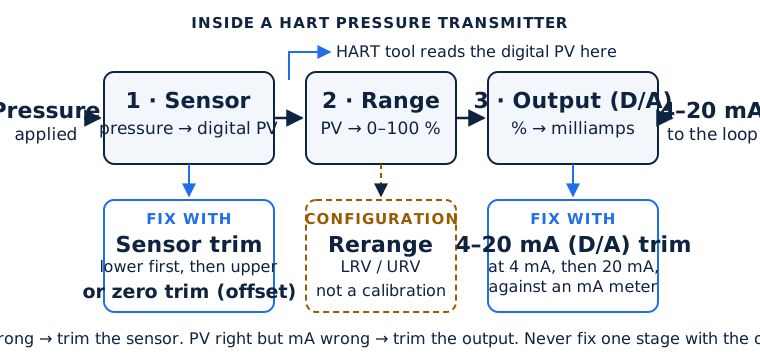
Inside a HART transmitter the signal passes through three stages: the sensor section converts pressure into a digital primary variable (PV); the range maps that PV onto 0–100 % using the lower and upper range values (LRV and URV); and the output section converts that percentage into an analog 4–20 mA current. Each has its own adjustment:
| Stage | Adjustment | What it changes |
|---|---|---|
| Sensor (pressure → digital PV) | Sensor trim (lower and upper) and zero trim | The pressure the transmitter reports – digitally and, through the output, in mA |
| Range (PV → %) | Rerange (LRV/URV) | Which pressures correspond to 4 and 20 mA. No reference involved: this is configuration, not calibration. |
| Output (% → mA) | 4–20 mA (D/A) trim or scaled D/A trim | Only the analog current; the digital PV is unaffected |
The rule that follows: if the reported pressure doesn't match the applied pressure, do a sensor trim; if the measured mA doesn't match what the transmitter says it is sending, do an output trim. Don't correct an error in one section by adjusting the other – it hides the problem and breaks the digital reading.
What you need
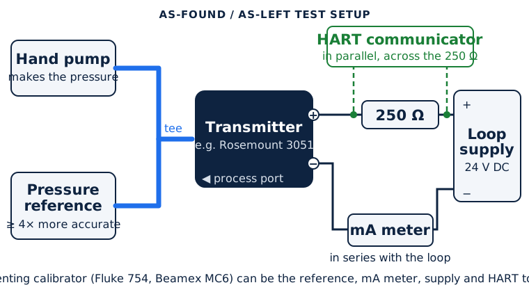
- A pressure reference at least four times more accurate than the transmitter. The 3051 manual asks for this, and a 4:1 test uncertainty ratio is also the fallback in ANSI/NCSL Z540.3. A hand pump with a pressure calibrator or pressure module is typical in the field; an absolute-pressure unit needs an accurate absolute reference.
- An accurate mA meter for the output check and D/A trim.
- A HART tool with the 3051's device description for its device revision: an AMS Trex, a 475 Field Communicator, or a documenting calibrator with HART (Fluke 754, Beamex MC6). See our comparison of HART tools.
- Loop power and at least 250 Ω between the transmitter and the supply. With 250 Ω in the loop, the 3051 manual calls for at least 16.6 V. Documenting calibrators can supply both. Our HART loop basics explains why.
Before you start
- Loop to manual and permit in place.
- Identify the transmitter. Note the model code: 3051C (coplanar – differential, gage or absolute), 3051T (in-line gage or absolute), 3051L (level with a direct-mount seal). The output code tells you the protocol: A is 4–20 mA HART; F, W and X are FOUNDATION Fieldbus, PROFIBUS PA and WirelessHART, which this guide doesn't cover. The 3051S is a different platform with its own manual.
- Connect your HART tool and read the device revision (on the device information screen). It decides which manual, DD and menus apply – see Fast Keys by device revision.
- Save the configuration, and check the security (write-protect) switch, HART lock and local operator interface (LOI) password. The security switch rejects every configuration change, whether over HART, the LOI or the buttons. To change a hardware switch: loop in manual, power off, then open the cover.
- Set damping to zero for the test (the HART Communication Foundation recommends it) and write down the original value to restore later.
- Choose test points and a tolerance. A five-point check at 0, 25, 50, 75 and 100 % of the range is common; to see hysteresis you need at least nine points – five going up and four coming back down. The tolerance usually comes from your site procedure or the transmitter's accuracy specification.
Step 1: the as-found test
- Isolate the transmitter from the process and connect the reference. On a differential-pressure transmitter with a manifold, the zero sequence is: close the low-side block valve first, open the equalizing valve (on a 5-valve natural-gas manifold, the high-side then the low-side equalize), and later reverse it – close the equalizer, then reopen the low-side block.
- At each test point, apply the pressure, let it stabilize (the manual suggests about 10 seconds for trims), and record the applied pressure, the PV read with your HART tool, and the mA output.
- Work out the output error in % of span: expected mA = 4 + 16 × (applied − LRV) ÷ (URV − LRV); error = (measured − expected) ÷ 16 × 100. The PV error is (PV − applied) ÷ (URV − LRV) × 100.
If every point is within tolerance, stop here: record the as-found data as your as-left data too. Comparing each as-left result with the next as-found shows how much the transmitter drifts – which is how you set a sensible calibration interval.
Step 2a: zero trim (offset only)
A zero trim is a single-point offset correction. Use it when the only error is an offset – typically from mounting position (a transmitter mounted other than horizontal sees the liquid head of its fill fluid) or from static line pressure on a differential unit. It keeps the slope, so it does not replace a full sensor trim.
- Do it with the transmitter in its final mounting position, the process vented or – on a DP transmitter – the high and low sides equalized with the equalizing valve open and any wet legs filled to their correct levels. The manual recommends a zero trim of the transmitter and manifold after installation.
- To remove the line-pressure effect on a DP transmitter, zero trim at line pressure (equalized).
- Never zero trim a 3051T absolute transmitter. Zero trim is zero-based and an absolute unit references absolute zero; use a lower sensor trim with an accurate absolute reference instead. If it happened by accident, recall the factory sensor trim.
- The transmitter will reject a zero trim that needs too large a correction. Older HART 5 manuals put the limit at 3 % of the upper range limit; the current manual only says the command may fail from excess correction.
- Units with the Digital Zero (DZ) option can be zeroed by holding the external zero button for at least two seconds, which the manual notes can be done in hazardous areas.
Step 2b: full sensor trim (lower, then upper)
A sensor trim is a two-point calibration: the lower trim corrects the offset and the upper trim corrects the slope, and the output is linearized between the two points.
- Start the lower sensor trim on your HART tool. Apply the lower pressure from your reference, let it stabilize, and enter the reference value when prompted.
- Then start the upper sensor trim: apply the upper pressure, let it stabilize and enter the reference value.
- Always do the lower trim first. Choose trim points at or outside the operating range (the LRV and URV are a natural choice).
For Range 4 and 5 differential transmitters used at high static pressure, the 3051 manual describes a systematic span shift with line pressure (about −0.95 % and −1 % of reading per 1,000 psi respectively) and shows how to enter a calculated upper-trim value to compensate. Ranges 0–3 don't need it.
Step 3: 4–20 mA (D/A) trim
The D/A trim adjusts the analog current at the 4 and 20 mA points to match your reference meter. It acts after the digital-to-analog conversion, so it changes only the analog signal.
- Connect an accurate mA meter at the transmitter's test terminals or in series in the loop. If you add a resistor, make sure the supply can still drive 20 mA.
- Start the D/A trim. The transmitter sets its output to 4 mA; enter what the meter reads. Repeat until the transmitter output and the meter agree.
- Do the same at 20 mA.
A scaled D/A trim does the same against another readout – for example the 0–100 % shown at the control system, or a voltage across a resistor – when you want the loop to agree end to end.
Step 4: as-left test and records
Run the same test points as the as-found test and confirm everything is inside tolerance. Restore the damping, re-enable the security switch or HART lock, return the manifold to service (close the equalizer, reopen the low-side block), confirm the output matches the process, and hand the loop back to operations. Record the tag, date, as-found and as-left results, the reference equipment and its calibration due date, and what you adjusted.
Re-ranging is not calibration
Changing the LRV and URV – by keypad, by applying pressure with the communicator, or with the local zero and span buttons – only decides which pressures map to 4 and 20 mA. No external standard is involved, so the HART Communication Foundation calls it a configuration change, not a calibration, and warns that "calibrating" with zero and span adjustments alone often corrupts the transmitter's internal digital readings. Re-range only to match the control system, then run the test points again. If a range change was made by mistake, the restore factory calibration functions put the sensor trim or the analog trim back to as shipped.
Fast Keys by device revision
Fast Keys are the numbered menu presses from the communicator's home screen. They depend on the transmitter's device revision and the DD loaded on your tool, so read the device revision first and use the manual that matches.
Device revision 9 (HART 5) and 10 (HART 7) – the 3051 with selectable HART 5/7
From the Rosemount 3051 reference manual 00809-0100-4007 (Device Dashboard DD). The trim keys are the same in HART 5 and HART 7 mode:
| Function | Fast Keys |
|---|---|
| Upper sensor trim | 3, 4, 1, 1 |
| Lower sensor trim | 3, 4, 1, 2 |
| Zero trim (digital zero trim) | 3, 4, 1, 3 |
| 4–20 mA (D/A) trim | 3, 4, 2, 1 |
| Scaled D/A trim | 3, 4, 2, 2 |
| Restore factory calibration | 3, 4, 3 |
| Range values / rerange with keypad | 2, 2, 2, 1 |
| Loop test (fix the output) | 3, 5, 1 |
The path behind 3, 4 is Service Tools → Maintenance: Pressure Calibration (upper, lower, zero), then Analog Calibration, then Restore Factory Calibration.
Older HART 5–only units (device revision 3)
The older manual 00809-0100-4001 lists two sets, depending on the DD style on your communicator. With the traditional DD: zero trim 1, 2, 3, 3, 1; lower sensor trim 1, 2, 3, 3, 2; upper sensor trim 1, 2, 3, 3, 3; D/A trim 1, 2, 3, 2, 1; rerange 1, 2, 3, 1. With the Device Dashboard DD, the trims sit under 3, 4 as above.
Device revision 11 and newer manuals
The 2024 edition of the 3051 manual (which adds device revision 11, with Bluetooth and a graphical display) describes trims by DD menu path – for example Device Settings → Calibration → Pressure and Device Settings → Calibration → Analog Output – rather than a Fast Key table. Follow the menu names on your tool.
On an AMS Trex
The Trex uses the same device description on a touchscreen, so the numbered menus above appear as the same named menus to tap through; its user guide does not use Fast Keys. The device-specific methods (sensor trim, D/A trim, restore factory calibration) are the same ones.
Doing it with a Fluke 754
The Fluke 754 combines the pressure reference (with a Fluke 750P-series pressure module), the mA measurement, loop power and basic HART functions, and it documents the results.
- Connect the mA jacks to the transmitter terminals and the pressure module to the process port. The 754 can power the loop through its internal 250 Ω resistor; with an external supply, put 230–270 Ω in series.
- Establish HART communication, then switch to the analog calibration mode (measure mA or PV) and run the As Found test; the 754 pre-fills the template from the transmitter's range.
- Choose Adjust to go to the HART service menu: Pressure Zero Trim, Sensor Trim (the 754 prompts you to zero the pressure module, then fetches its reading as the reference) and Output Trim (it fetches its own mA reading into the trim).
- Run the As Left test and save the results for upload.
Note: the 754 performs a full sensor trim only on the transmitter models it is programmed for; on others it offers zero trim and output trim. Fluke also notes that measuring across a transmitter's test diode doesn't give the best mA accuracy.
Doing it with a Beamex MC6
The MC6 has internal pressure modules, a 24 V loop supply with HART impedance built in (with an external supply, add 250 Ω) and a DD-based HART communicator.
- Connect the transmitter to the MC6's loop supply and pressure port, and select the transmitter in the documenting calibrator.
- Run the As Found calibration.
- If adjustment is needed, open the HART communicator from within the calibration, run the device's trim method (sensor trim or D/A trim), and enter the MC6's reference reading when the method asks for it.
- Run the As Left calibration and transfer the results to Beamex CMX or your calibration software.
Many transmitter menus call a trim "calibration"; whatever the label, you need the reference for the numbers you enter.
How often to calibrate
There is no universal interval. The 3051 manual shows how to estimate one from the required performance, the transmitter's stability and the operating conditions (static pressure, ambient temperature). Your own as-found history is the best evidence: if the as-found results are consistently well inside tolerance, the interval can often be extended; if they drift toward the limit, shorten it.
Always follow the manufacturer's manual and your site's procedures. Fast Keys, menu names and limits depend on the device revision, the DD and your tool; the manual for your transmitter takes precedence over this summary.
Sources
- Emerson, Rosemount 3051 Pressure Transmitter Reference Manual 00809-0100-4007 (HART 5/7 selectable; current edition)
- Emerson, Rosemount 3051 Reference Manual 00809-0100-4001 (HART 5, device revision 3)
- Emerson, Rosemount 3051 Product Data Sheet 00813-0100-4001
- HART Communication Foundation, Calibrating HART Transmitters (HCF_LIT-054)
- Emerson, 475 Field Communicator User's Manual
- Emerson, AMS Trex Device Communicator User Guide
- Fluke, 754 HART Mode Users Guide
- Fluke, 753/754 Users Manual
- Fluke, HART smart pressure transmitter calibration
- Beamex, MC6 User Manual
- Beamex, Calibration of a HART transmitter and common misconceptions about the HART communicator
- Transcat, Understanding Test Uncertainty Ratio (quoting ANSI/NCSL Z540)
Replacing a transmitter or stocking a spare? See our Rosemount and Emerson stock, browse transmitters and test equipment, search for 3051, or request a quote with the full model code.
Frequently asked questions
What is the difference between a sensor trim and a zero trim on a Rosemount 3051?
A sensor trim is a two-point calibration of the pressure measurement: the lower trim corrects the offset and the upper trim corrects the slope, against a pressure reference. A zero trim is a single-point offset correction for mounting position or line pressure; it keeps the slope, so it does not replace a full sensor trim.
Is re-ranging a 3051 the same as calibrating it?
No. Changing the lower and upper range values only decides which pressures correspond to 4 and 20 mA. No reference standard is involved, so it is a configuration change, not a calibration. Calibration compares the transmitter with a reference and trims the sensor or output if they disagree.
Can I zero trim a Rosemount 3051T absolute pressure transmitter?
No. Emerson's manual says not to, because zero trim is zero-based and an absolute unit references absolute zero. Use a lower sensor trim with an accurate absolute pressure reference instead.
What are the Fast Keys for a 3051 sensor trim?
On a 3051 with selectable HART 5/7 (device revisions 9 and 10), the manual lists upper sensor trim 3, 4, 1, 1; lower sensor trim 3, 4, 1, 2; zero trim 3, 4, 1, 3; and D/A trim 3, 4, 2, 1. Older and newer device revisions use different keys or menu paths, so check the device revision first.
In which order should I trim a 3051?
Test first and adjust only what is out. For a sensor trim, always do the lower trim before the upper trim. Correct the sensor and the 4-20 mA output separately: if the reported pressure is wrong, trim the sensor; if the measured mA is wrong, trim the output.