HART lets a digital conversation ride on the same two wires as a 4–20 mA signal. That is why a technician can read a transmitter's configuration or run a trim without disturbing the analog value the control system uses. But the conversation only works when the loop meets a few simple conditions – and most "the communicator can't find the device" calls come down to one of them.
Key takeaways
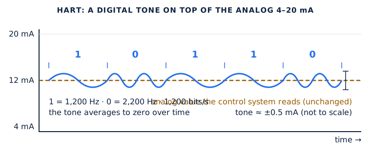
- HART is a small 1,200/2,200 Hz signal on top of the 4–20 mA; it averages to zero, so it does not change the analog value.
- The loop needs at least 230 Ω, usually a 250 Ω resistor; without it, the communicator can't hear the device.
- Connect the communicator across the transmitter's terminals or across the loop resistor – in parallel, without breaking the loop.
- Put the control loop in manual or out of service before you change configuration or drive the output.
- In hazardous areas, only intrinsically safe tools, used as part of a properly designed IS loop.
Safety first: follow your site's lockout/tagout and permit procedures; before changing a device's configuration, running a trim or forcing its output, put the control loop in manual or out of service and tell operations; check the output before returning to automatic. Treat every loop in a hazardous area as part of an intrinsically safe system – connect only approved equipment and follow your site's permit procedures.
What the HART signal is
HART (Highway Addressable Remote Transducer) uses frequency-shift keying based on the Bell 202 standard: a 1,200 Hz tone represents a 1 and a 2,200 Hz tone a 0, at 1,200 bits per second. The tone is small – about ±0.5 mA – and averages to zero over time, so the 4–20 mA value the control system reads is unaffected. Because the digital and analog signals share the wire, you can talk to a transmitter while the loop keeps running.
- Masters. A loop can have two HART masters at once: the primary (usually the DCS, PLC or asset-management system) and a secondary, such as your handheld.
- Multidrop. Several transmitters can share one pair – up to 15 in HART 5 and 62 in HART 7 – each with its own address and its current fixed (typically 4 mA), so the loop becomes all-digital. A transmitter at a nonzero polling address may hold its output at a fixed current, which matters when you expect a live 4–20 mA.
- Burst mode. A device can be set to broadcast its data continuously instead of waiting to be asked. It is optional and is switched off with a command.
The 250 Ω resistor: why HART needs it
The transmitter creates the HART signal by varying its current. That current becomes a voltage the communicator can read only if it flows through enough resistance. The HART specification requires a minimum loop resistance of 230 Ω, and a 250 Ω resistor is the usual choice. In most installed loops, the control system's input card already provides it. On a bench, with just a power supply and a transmitter, it usually does not – which is why a communicator can "see" nothing.
There is an upper limit too. Total loop resistance, including the cable, is typically between 230 and 1,100 Ω, and in practice the maximum is set by how much voltage the supply can provide: the transmitter needs its own minimum terminal voltage (its lift-off voltage, often around 10–12 V – check the data sheet) even at 20 mA or more, after the resistor and cable have taken their share.
| Tool | Loop power and resistor |
|---|---|
| Emerson 475 | No loop power. Needs an external supply and at least 250 Ω; add the optional series resistor if the loop has less. |
| Emerson AMS Trex (Device Communicator Plus module) | Can switch in its own resistor (the Trex 2 chooses 250 or 500 Ω automatically) and can power one HART device, using a 167 Ω resistor because of intrinsic-safety limits. |
| Fluke 754 | Its 26 V loop supply includes an internal 250 Ω resistor. With an external supply, put 230–270 Ω in series. |
| Beamex MC6 | Built-in 24 V supply with a selectable HART impedance, so no external resistor is needed. With an external supply, add 250 Ω. |
A quick check with a meter: across a 250 Ω resistor you should see about 1 V at 4 mA and 5 V at 20 mA. If you see much less, the resistance is too low for HART.
Where to connect
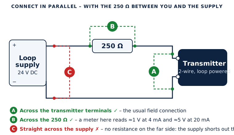
HART masters connect in parallel, so you never need to break the loop to talk to a device. Connect the communicator:
- across the transmitter's terminals in the field;
- across the loop resistor or at the control system's terminations; or
- at any wiring termination point on the loop – as long as the loop resistance is on the far side of your connection from the power supply.
Most communicator HART leads are not polarity-sensitive. To measure the loop current with a calibrator, though, you do need to be in series – either by breaking the loop or, on transmitters that have them, using the test terminals. When a calibrator powers the loop (the Fluke 754 and Beamex MC6 can), it powers one device, and you must not add a second supply at the same time.
Make the process safe first
Everything a technician does with a HART tool can move the 4–20 mA signal: a trim, a loop test that forces the output, a change of range or units, even a wrong keypress. Emerson's communicator manuals say to put the control loop in manual or out of service before applying changes, and to check the output before returning to automatic. In practice:
- Agree the work with operations and follow your site's permit and bypass procedures.
- Put the controller in manual (or bypass the interlock or trip, if the procedure allows) before connecting.
- Save or record the transmitter's configuration before changing anything.
- When you finish, confirm the output matches the process, remove any forced values, and hand the loop back.
Hazardous areas and intrinsic safety
The FieldComm Group's HART application guide makes a point worth remembering: no single field device or wire is intrinsically safe on its own – a loop is intrinsically safe only as part of a properly designed and certified IS system. For test equipment that means:
- Use only tools certified for the area: the intrinsically safe versions of the AMS Trex or 475, or a calibrator built for it such as the Beamex MC6-Ex. The standard Fluke 754 and Beamex MC6 are not approved for hazardous areas.
- Don't charge batteries, swap batteries or connect USB or AC adapters in the hazardous area.
- A handheld adds a little voltage (up to about 2 V, per the HART guide) to an IS loop; this is considered in the IS system design, which is another reason to use only approved tools.
- Manufacturers' brochures sometimes say an IS tool avoids hot-work permits. Your site's permit system decides that, not the brochure.
"No device found": a quick checklist
- Is the transmitter powered? Most need at least 4 mA and roughly 12 V at their terminals.
- Is there at least 230–250 Ω between your connection and the power supply?
- Is the polling address right? Try address 0, then scan 1–15 (or 0–63 on HART 7) for multidrop loops.
- Is another master, or burst mode, crowding the line? A busy primary master or a bursting device can slow a handheld's response.
- Does your tool have the device description for that device revision? Without it, you may get only generic functions.
- Is the wiring noisy or very long? Excessive cable capacitance and noise both degrade the HART signal.
Next steps: see how to calibrate a Rosemount 3051, how to calibrate an Endress+Hauser TMT82, and which HART tool to use.
Always follow the manufacturer's manual and your site's procedures. This guide is a general reference; the documentation for your transmitter, communicator and calibrator takes precedence.
Sources
- FieldComm Group (HCF), HART Application Guide, HCF_LIT-039
- Samson, HART Communications, Technical Information L452
- Emerson, 475 Field Communicator User's Manual
- Emerson, AMS Trex 2 User Guide
- Emerson, AMS Trex product data sheet
- Fluke, 754 HART Mode Users Guide
- Fluke, 753/754 Users Manual
- Beamex, MC6 brochure
- Beamex, MC6 User Manual
- Beamex, MC6-Ex brochure
Need a transmitter or loop component? Browse transmitters and test equipment, see our Rosemount stock, or request a quote.
Frequently asked questions
Why does HART need a 250 ohm resistor?
The transmitter creates the HART signal by varying its current, and the communicator reads it as a voltage across the loop resistance. The HART specification needs at least 230 ohms; 250 ohms is the usual value.
Where do I connect a HART communicator?
In parallel: across the transmitter's terminals, across the loop resistor, or at a termination point, with the loop resistance between your connection and the power supply. You don't need to break the loop.
Does HART communication change the 4-20 mA signal?
No. The HART tones average to zero, so the analog value is unaffected. But a trim, a loop test or a configuration change can move the output, so put the loop in manual first.
Why can't my communicator find the transmitter on the bench?
The most common cause is missing loop resistance: a bench power supply and transmitter alone usually have less than 250 ohms. Also check the supply voltage, the polling address and the device description.