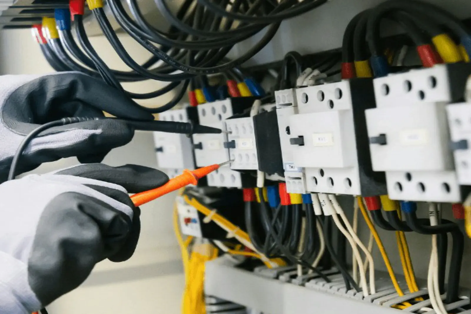
The iTEMP TMT82 is Endress+Hauser's two-channel HART 7 temperature transmitter. It comes as a head transmitter for a DIN-style terminal head, a DIN rail version and a field housing, and it accepts RTDs (2-, 3- or 4-wire on sensor 1), thermocouples, resistance and millivolt inputs. Calibrating it well comes down to three things: knowing which adjustment fixes which error, simulating the input correctly, and recording the results before and after you change anything.
Key takeaways
- Check it before you touch it: record an as-found test at several points, then adjust only if it is out of tolerance, then record an as-left test.
- Sensor trimming corrects the measured temperature (digital value and output); current trimming corrects only the 4–20 mA output. Changing the range (LRV/URV) is not calibration.
- For the best accuracy with a calibrated RTD, enter its Callendar-Van Dusen coefficients (sensor-transmitter matching) instead of trimming.
- Menu names changed between firmware 01.01 and 01.02; match the DD/DTM to the device revision and check the path on your tool.
Safety first: follow your site's lockout/tagout and permit procedures; put the control loop in manual (or otherwise make it safe) and tell operations before you disconnect a sensor or drive the output – the 4–20 mA signal will move. In a hazardous area, use only equipment approved for it, follow the transmitter's Ex safety instructions (the XA document named on its nameplate) and your site's permit procedures. Never open a flameproof housing in an explosive atmosphere.
What you need
| Item | Why |
|---|---|
| RTD / thermocouple simulator (or a documenting calibrator such as a Fluke 754 or Beamex MC6) | Sources a known resistance or millivolt signal to the transmitter's input. |
| Accurate mA meter (often the same calibrator) | Reads the 4–20 mA output. For current trimming it must be more accurate than the transmitter. |
| Loop power supply and at least 250 Ω in the loop | The transmitter needs loop power; HART communication needs at least 250 Ω of loop resistance. Many documenting calibrators provide both. |
| A HART configuration tool with the right driver | A handheld (for example AMS Trex or a 475 with the TMT82 DD), FieldCare or DeviceCare with a HART modem such as the Commubox FXA195, or Field Xpert. |
| Test leads of the correct type | Copper leads for RTD/resistance; thermocouple-grade wire of the same type for thermocouple tests. |
| For a loop (sensor + transmitter) calibration: a dry-block or bath and a reference thermometer | Checks the sensor and transmitter together at real temperatures. |
A common rule of thumb is that your reference should be several times more accurate than the tolerance you are checking – a 4:1 ratio is the usual target. For the TMT82 with a Pt100 over 0 to 200 °C, Endress+Hauser's manual gives a typical accuracy of about 0.08 °C for the digital value and about 0.1 °C at the current output, so check your simulator's specification against the tolerance you intend to apply.
Before you start
- Make the loop safe. Put the controller in manual or bypass the interlock under your site's procedure.
- Read the nameplate. Note the order code, the Ex approval and its XA document, and the firmware version.
- Connect your configuration tool and save the configuration (sensor type, connection type, units, range, damping, sensor trimming and linearization settings). You will want it if anything needs restoring.
- Check write protection. The TMT82 can be locked two ways: a WRITE LOCK DIP switch on the back of the optional display, which takes priority and stays active when the display is removed, and a software access code under Setup → Advanced setup → Administration. The locking status is shown under Setup → Advanced setup. Unlock only with permission.
- Decide your test points and tolerance. Five points across the range (0, 25, 50, 75 and 100 %) are typical; use your site's calibration procedure if it specifies something else.
Step 1: the as-found test (transmitter only, simulated input)
Wire the simulator to match the transmitter's configuration
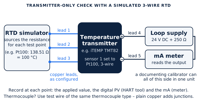
- RTD: wire the simulator the same way the transmitter is configured – 2-, 3- or 4-wire (sensor 1 accepts 4-wire; sensor 2 takes 2- or 3-wire). A 3-wire RTD check needs five leads: three for the simulated RTD and two for the mA measurement. If the transmitter is set to 2-wire, it may have a lead-resistance compensation value entered (0–30 Ω); take that into account.
- Thermocouple: use test wire of the same thermocouple type. Plain copper leads create extra junctions that the cold-junction compensation cannot correct. Check how the transmitter's reference junction is configured (internal measurement, a preset value, or sensor 2 as an external reference) and set the simulator to match. The DIN rail version reaches its rated accuracy with the internal reference junction only when mounted vertically.
- Pulsed sensor current: some transmitters pulse the current they use to read an RTD, and not every simulator follows a pulse correctly. Check that your simulator is specified for pulsed excitation if readings look unstable.
Record the readings
At each test point, apply the simulated temperature, wait for the reading to settle (allow for the configured damping), and record three things: the applied value, the transmitter's digital PV (from the configuration tool) and the mA output (from the meter). Going up through the points and back down shows any hysteresis. Work out the error of the output as a percentage of span:
Expected mA = 4 + 16 × (applied − LRV) ÷ (URV − LRV)Error (% of span) = (measured mA − expected mA) ÷ 16 × 100
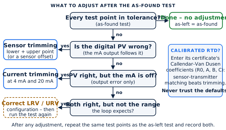
If every point is inside tolerance, you are done: the as-found result is also the as-left result. Adjust only what is out.
Step 2: decide what to adjust
| What you see | Likely cause | Adjustment |
|---|---|---|
| The digital PV is wrong, and the mA output follows it | Input (measurement) error | Sensor trimming (or a sensor offset for a single-point correction) |
| The digital PV is right, but the mA output is off | Output (D/A) error | Current trimming at 4 and 20 mA |
| Both are right, but the range is not what the loop expects | Configuration, not calibration | Correct the LRV/URV to match the control system – then retest |
| You have a calibrated RTD with a certificate | Sensor interchangeability error | Sensor-transmitter matching (Callendar-Van Dusen coefficients) |
Step 3: sensor trimming (two-point input correction)
Sensor trimming corrects the transmitter's reading at a lower and an upper point (slope and offset). It changes the measured value – so the digital PV, the display and the current output all follow – but not the measuring range. In firmware 01.02 (manual BA01028T edition 26.24) the parameters are under Expert → Sensors → Sensor 1 (or 2) → Sensor trimming:
- Set Sensor trimming to Customer-specific.
- Apply a known, stable temperature near the bottom of the range. Endress+Hauser's manual describes doing this with the real sensor in a water or oil bath; with transmitter-only calibration, technicians apply the equivalent simulated value instead.
- Enter that reference temperature as Sensor trimming lower value.
- Repeat near the top of the range and enter Sensor trimming upper value. The Sensor trimming min span parameter shows the smallest allowed distance between the two.
Setting Sensor trimming back to Factory setting restores the original linearization. For a simple one-point shift, a sensor offset (−10 to +10) is also available under Setup → Advanced setup → Sensors or Expert → Sensors → Sensor n. To see the raw, unlinearized input (ohms or millivolts) while you work, use Expert → Diagnostics → Measured values → Sensor n raw value.
Endress+Hauser notes that trimming corrects only at the two chosen points and is less accurate than sensor-transmitter matching.
Step 4: current (4–20 mA) trimming
Current trimming adjusts only the analog output. It does not change the digital value sent over HART, so after an output trim the display and the control system can disagree if the input is also off – fix input errors with sensor trimming first. The manual's procedure, paraphrased:
- Put an ammeter that is more accurate than the transmitter in the loop. On the DIN rail version you can measure between the Test and – terminals.
- Turn on current output simulation at 4 mA (Diagnostics → Simulation → Current output simulation, then set the value) and note what the meter reads.
- Set the simulation to 20 mA and note the reading.
- Enter the two measured values in Current trimming 4 mA and Current trimming 20 mA (Setup → Advanced setup → Current output, or Expert → Output). The allowed entries are about 3.85–4.15 mA and 19.85–20.15 mA.
- Switch the simulation off.
Current trimming is not available when the transmitter is in SIL mode. Handheld HART tools can also reach it through the standard loop-current trim commands, labelled by the tool (for example "D/A trim" or "loop current trim").
Step 5: the as-left test and records
Repeat the test points exactly as in the as-found test and confirm every point is inside tolerance. Record the date, the instrument tag, the as-found and as-left results, the reference equipment used with its calibration due date, and any adjustment you made. The TMT82 also has a calibration counter (up to 365 days) that raises a Calibration interval diagnostic when it runs out – set it to your calibration interval if you use it. Finally, restore write protection and return the loop to automatic with operations' agreement.
Sensor-transmitter matching with Callendar-Van Dusen coefficients
A standard Pt100 follows the IEC 60751 curve only within its tolerance class. For class A that tolerance is ±(0.15 + 0.002·|t|) °C, and for class B ±(0.3 + 0.005·|t|) °C – at 100 °C, about ±0.35 °C and ±0.8 °C. If the RTD has been calibrated, its certificate gives its own Callendar-Van Dusen coefficients (R0, A, B and C). Entering them makes the transmitter use that sensor's real curve instead of the standard one, which Endress+Hauser says significantly improves system accuracy.
In firmware 01.02 the coefficients are under Expert → Sensors → Sensor n → Linearization:
- Set the sensor type to RTD platinum (Callendar/Van Dusen) and the connection type (for example 3-wire).
- Set the sensor's lower and upper limits.
- Enter R0 and the coefficients A, B and C exactly as printed on the certificate.
- Repeat for sensor 2 if it is used.
Watch the defaults. The coefficients pre-set in the transmitter are not the IEC 60751 standard values (IEC 60751 uses A = 3.9083 × 10⁻³, B = −5.775 × 10⁻⁷, C = −4.183 × 10⁻¹²), so always overwrite them with your certificate's values rather than assuming the defaults are "standard". Copper and nickel RTDs use a separate polynomial (R0, A, B) in the same menu.
Re-ranging is not calibration
Changing the lower and upper range values (Setup → Lower range value / Upper range value) only changes which temperatures correspond to 4 and 20 mA. It does not correct a measurement error, and adjusting the output while ignoring the input side is not a proper calibration either. Change the range only to match what the control system expects, and then run the test points again.
Transmitter-only or loop calibration?
Simulating the input checks the transmitter alone. It is quick, needs no heat source and is the right way to prove the electronics. It says nothing about the sensor. A loop calibration puts the actual sensor in a dry-block or bath next to a reference thermometer, so it covers the sensor, the transmitter, the wiring and the reading in the control system together. For quality- or safety-critical measurements, many sites do both: simulate to check the transmitter, then check the sensor at one or more real temperatures. In a dry-block, put the reference probe at the same depth as the sensor, insert both deep enough, and give the block time to stabilize – rushing it is one of the biggest sources of error.
Menu paths by firmware version
The TMT82 has had firmware 01.00, 01.01 and 01.02. The manual for 01.01 (BA01028T edition 17.17) corresponds to device revision 2; the manual for 01.02 (edition 26.24) to device revision 3. Your DD or DTM must match the device revision, and some menu names differ between them:
| Function | Firmware 01.02 (manual 26.24) | Firmware 01.01 (manual 17.17) |
|---|---|---|
| Sensor trimming, linearization | Expert → Sensors → Sensor n → … | Expert → Sensor → … (singular) |
| Current output simulation | Diagnostics → Simulation → Current output simulation | Diagnosis → Simulation → Simulation current output |
| Current trimming | Setup → Advanced setup → Current output, or Expert → Output | Check your manual edition |
These are the paths Endress+Hauser gives for its own operating tools such as FieldCare. A handheld communicator running the TMT82 device description may group and label the same parameters differently, so confirm the path on your tool rather than relying on a list.
Which tool to connect with
- FieldCare or DeviceCare on a laptop, with the TMT82 DTM and a HART modem. The Commubox FXA195 is a USB HART modem with a switchable 250 Ω resistor. Endress+Hauser device drivers are under Downloads on its website.
- A HART handheld with the TMT82 device description: Emerson's AMS Trex (which updates its drivers through its own update function) or the older 475 Field Communicator. See our comparison of HART communicators and documenting calibrators.
- Field Xpert, Endress+Hauser's own tablet configurator. The SMT70 has been succeeded by the SMT70B.
- A documenting calibrator with HART (Fluke 754, Beamex MC6) can simulate the input, read the output, talk HART and record the as-found/as-left results in one instrument.
The TMT82 is the HART version. Its PROFIBUS PA and FOUNDATION Fieldbus relatives (TMT84 and TMT85) are separate products with their own manuals, and Endress+Hauser's Bluetooth/SmartBlue transmitters are the TMT71 and TMT72.
Hazardous areas
Check the nameplate for the approval and its safety instructions (XA document), which are part of the manual. In hazardous areas the CDI service interface must not be used for configuration, and the terminal head cover must be secured to keep the explosion protection. Use only intrinsically safe or otherwise approved test equipment in the zone, and follow your site's permit-to-work rules. The TMT82 is not repairable; a failed unit is replaced.
Always follow the manufacturer's manual and your site's procedures. This guide summarizes the manufacturer's documentation and common practice for planning and reference; menu paths and limits depend on the firmware, the device revision and the operating tool, and the manual for your unit takes precedence.
Sources
- Endress+Hauser, iTEMP TMT82 Operating Instructions, BA01028T/09/EN/26.24 (firmware 01.02)
- Endress+Hauser, iTEMP TMT82 Operating Instructions, BA01028T/09/EN/17.17 (firmware 01.01)
- Endress+Hauser, iTEMP TMT82 Technical Information TI01010T
- Endress+Hauser, Safety Instructions XA01007T (TMT71/72/82/84/85)
- Endress+Hauser, Commubox FXA195 product page
- Endress+Hauser Learning Center, RTD measurement accuracy
- Fluke, Calibrating a HART temperature transmitter
- Fluke, Best practices for process temperature calibration
- Beamex, How to calibrate an RTD HART temperature transmitter
- Beamex, Thermocouple cold (reference) junction compensation
- Beamex, How to calibrate temperature sensors
- Texas Instruments, A Basic Guide to RTD Measurements (SBAA275A) – IEC 60751 coefficients and tolerance classes
Looking for a transmitter, a spare sensor or test equipment? Browse transmitters, temperature sensors and test equipment, see our Endress+Hauser stock, search by part number, or request a quote.
Frequently asked questions
What is the difference between sensor trimming and current trimming on a TMT82?
Sensor trimming corrects the measured temperature at a lower and an upper point, so the digital value, the display and the output all follow. Current trimming adjusts only the 4 and 20 mA output and does not change the digital HART value.
Where are the Callendar-Van Dusen coefficients entered on a TMT82?
In firmware 01.02, under Expert, Sensors, Sensor n, Linearization, with the sensor type set to RTD platinum (Callendar/Van Dusen). Enter R0, A, B and C from the sensor's calibration certificate.
Are the TMT82's default Callendar-Van Dusen coefficients the IEC 60751 values?
No. The pre-set coefficients differ from the IEC 60751 standard values, so always overwrite them with the values on your sensor's certificate.
How do I simulate a 3-wire RTD for a TMT82?
Wire the RTD simulator exactly as the transmitter is configured: three leads for the simulated RTD, plus two for the mA measurement. Sensor 1 also accepts 4-wire; sensor 2 takes 2- or 3-wire.
Can I calibrate a TMT82 with an AMS Trex or 475?
Yes, with the TMT82's device description loaded for its device revision. Endress+Hauser's own tools are FieldCare or DeviceCare with a HART modem such as the Commubox FXA195, and Field Xpert.